
Network Management v2.51
Network Management v2.5.3
Requirements and functions:
Scope of the OSEK Network Management
Embedding of the Network Management:
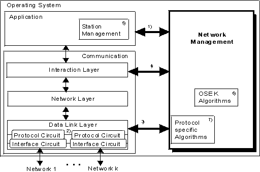
OSEK NM defines a set of services for node monitoring. The next
figure shows how the NM is embedded into a system. It is also shown that the NM has to be
adapted to specific requirements of the bus system used or to the resources of the nodes.

Figure 1 interface and algorithms responsibility
1) API, fixed by OSEK
2) several busses connected to one mController
3) interface to DLL - COM specific, protocol specific
4) interface to COM Interaction Layer
5) station management (outside OSEK, see text below)
6) OSEK algorithms
7) protocol specific management algorithms
OSEK/VDX NM
- interface to interact with the application (API)
- algorithm for node monitoring
- OSEK internal interfaces (NM <-> COM, ...)
- algorithm for transition into sleep mode
- NM protocol data unit (NMPDU)
adaptation to bus protocol specific requirements
- CAN, VAN, J1850, K-BUS, D2B, ...
- error handling, e.g. bus-off handling in a CAN, transmission line
error handling
- interpretation of the status information, e.g. overrun or error
active/passive in a CAN
adaptation to node resources
- scaling of the NM as a requirement of the node
- application specific usage of the NM services
adaptation to hardware specific requirements
- adaptation to a protocol circuit and a physical layer circuit
e.g. switching the bus hardware to one of the possible physically
power save modes
station management (system specific algorithms)
There are a variety of additional tasks to co-ordinate a network.
Those are not described by OSEK, since they are system dependent. Hence these tasks are
done by the application, e.g. by a module called station management.
Philosophy of Node Monitoring
Node Monitoring is used to inform the application about the nodes on
the network. Thus the application can check with the appropriate service if all stations
required for operation are present on the network.
Concept
Node Monitoring
OSEK-NM supports the direct node monitoring by dedicated NM communication. A node is a
logical whole to which a communication access is possible. A micro processor with two
communication modules connected to two different communication media (e.g. low speed CAN
and a high speed CAN) represents two nodes from the OSEK point of view.
The rate of the NM communication is controlled across the network (minimisation of bus
load and consumption of resources) and the messages are synchronised (avoiding negative
effects on application data by message bursts).
Every node is actively monitored by every other node in the network. For this purpose the
monitored node sends a NM message according to a dedicated and uniform algorithm.
Direct node monitoring requires a network-wide synchronisation of NM messages. For this
purpose a logical ring is used.
Logical ring:
In a logical ring the communication sequence is defined independent from the network
structure. Therefore each node is assigned a logical successor. The logically first node
is the successor of the logically last node in the ring.
Thus the decentralised control of the overall amount of NM messages is ensured and the bus
load due to these messages is determined. The communication sequence of the logical ring
synchronises NM communication. Any node must be able to send NM messages to all other
nodes and receive messages from them.
Principle
The direct NM transmits and receives two types of messages to build the logical ring. An alive message registrates a new transmitter to the logical ring. A ring message is responsible for the synchronised running of the logical ring. It will be passed from one node to another (successor) node.
State of a node
A monitoring node is able to distinguish 2 states of a monitored node.
A monitoring node is able to distinguish 2 states of itself.
According to system design aspects, direct monitoring of the nodes may be impossible or
non-desirable. This could be the case for example for very simple or time-critical
applications.
Therefore mechanism of indirect monitoring is introduced. This network management is based
on the use of monitored application messages. Therefore indirect monitoring is limited to
nodes that periodically send messages in the course of normal operation.
In this case, a node emitting such a periodical message is monitored by one or more other
nodes receiving that message. Nodes whose normal functionality is limited to receiving
must send a dedicated periodic message in order to be monitored.
Concept
Node Monitoring
Indirect network management uses monitoring of periodic application messages to determine states of nodes connected to the network. It does not make use of dedicated network management messages.
Node states
Emitter states:
For a given node i, emitter states are used to check that node i, which is supposed to
emit information on the bus, is indeed able to transmit.
Node state "mute" can be extended to several state types (see "Extended node states").
Receiver states:
A given node i monitors a subset of k nodes on the network: node i monitors only source
nodes, from which it receives cyclic application messages. Therefore, node i will maintain
a set of k receivers states, where k is the number of source nodes monitored by node i.
Receiver states are used to check that node i, which is supposed to receive information
from its k other source nodes, indeed receives information from each of its sources.
Node state "absent" can be extended to several state types (see
"Extended node states").
Extended Node states
Extended Emitter states:
Extended Receiver states:
Last Update: 29.07.2004